AI-Driven Cleanroom HVAC Optimization: Cutting 25% Energy Without Compromising Yield
Cleanroom HVAC systems consume 35-45% of total fab energy, yet most operate on fixed setpoints. This guide explores how AI reduces HVAC energy by 15-25% while maintaining ISO Class 5 cleanliness.
Key Takeaway
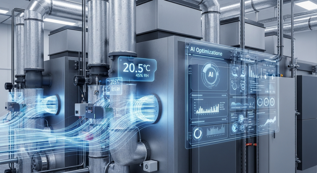
AI HVAC optimization reduces cleanroom energy consumption by 15-25%. HVAC accounts for 30-40% of total fab energy. Digital twin modeling maintains temperature control at ±0.5°C and humidity at ±2% RH while achieving significant energy savings.
The HVAC Energy Problem in Semiconductor Cleanrooms
Cleanroom HVAC systems are the single largest energy consumer in semiconductor fabrication facilities, accounting for 35–45% of total fab energy. For a 300mm fab consuming 100 MW, this means 35–45 MW is dedicated solely to maintaining the pristine air quality, temperature, and humidity conditions that advanced chip manufacturing demands.
Despite this enormous energy footprint, most cleanroom HVAC systems operate on fixed setpoints established during facility qualification — setpoints that remain unchanged whether the fab is running at 100% utilization or 60%, whether it is a cool winter night or a sweltering summer afternoon. This static approach to a fundamentally dynamic problem represents one of the largest energy optimization opportunities in semiconductor manufacturing.
Understanding Cleanroom HVAC Architecture
Before exploring AI optimization strategies, it is essential to understand the three primary HVAC subsystems in a semiconductor cleanroom and their respective energy profiles:
Make-Up Air Units (MAU)
MAUs condition and filter outside air to replace exhausted air from the cleanroom. They handle the heaviest thermal and moisture loads, as they must cool and dehumidify ambient air to cleanroom specifications. MAUs typically account for 25–35% of total HVAC energy and are highly sensitive to outdoor weather conditions — a 10°C increase in outdoor temperature can raise MAU energy consumption by 15–20%.
Fan Filter Units (FFU)
FFUs are the workhorses of cleanroom air quality. Hundreds or thousands of FFUs mounted in the cleanroom ceiling provide HEPA-filtered, unidirectional airflow at velocities of 0.3–0.5 m/s. They maintain the laminar flow pattern that keeps particle counts within ISO Class 5 specifications. FFUs account for 30–40% of HVAC energy and operate continuously, typically at fixed speed regardless of actual contamination risk.
Air Handling Units (AHU) and Recirculation Systems
Recirculation AHUs condition return air from the cleanroom subfab, providing precise temperature and humidity control. They work in concert with MAUs and FFUs to maintain environmental setpoints. AHUs and associated cooling coils account for 25–35% of HVAC energy, with their load varying based on process tool heat output and cleanroom occupancy.
| HVAC Subsystem | % of HVAC Energy | Primary Function | AI Optimization Potential |
|---|---|---|---|
| Make-Up Air Units (MAU) | 25–35% | Outdoor air conditioning | 15–25% reduction |
| Fan Filter Units (FFU) | 30–40% | Cleanroom air filtration & flow | 20–30% reduction |
| Recirculation AHU | 25–35% | Temperature & humidity control | 10–20% reduction |
| Exhaust Systems | 10–15% | Process exhaust & make-up | 10–15% reduction |
Why Traditional PID Control Wastes Energy
Cleanroom HVAC systems universally employ PID (Proportional-Integral-Derivative) controllers for temperature, humidity, and pressure regulation. While PID control is reliable and well-understood, it has fundamental limitations that drive energy waste in semiconductor cleanrooms:
Fixed Setpoints with No Context Awareness
PID controllers maintain a single setpoint regardless of context. A cleanroom bay with all tools in idle mode receives the same air change rate and temperature control as a bay running full production. The controller has no awareness of production state, tool activity, or occupancy — it simply maintains its programmed setpoint with conservative margins.
No Coordination Between Subsystems
Each PID loop operates independently. The MAU controller does not coordinate with FFU speeds, AHU cooling coil valves do not anticipate chiller load changes, and exhaust fan speeds are not linked to actual chemical usage. This lack of coordination leads to simultaneous heating and cooling, over-ventilation of low-risk zones, and suboptimal chiller loading — all common forms of energy waste.
No Predictive Capability
PID control is inherently reactive. When a process tool ramps from standby to production, it generates a thermal load increase that the HVAC system only detects after temperatures begin to rise. The PID controller then responds, but the lag means the system overshoots — consuming excess energy to recover the setpoint. This reactive cycle repeats continuously, wasting energy with every load transition.
Conservative Safety Margins
Because PID systems cannot predict or adapt, facility engineers build in substantial safety margins. Air change rates are set 20–30% above the minimum required to meet ISO specifications. Temperature control bands are tightened beyond process requirements. These margins guarantee compliance but at a steep energy cost — typically 15–25% more energy than what would be needed with intelligent, adaptive control.
The AI Approach: Dynamic, Predictive, Closed-Loop HVAC Optimization
AI-driven HVAC optimization replaces the static, reactive paradigm of PID control with a dynamic, predictive, and coordinated approach. Here is how each capability translates to energy savings:
Dynamic Air Change Rate (ACH) Control
The most impactful AI optimization strategy is dynamic adjustment of air change rates based on real-time contamination risk assessment. Traditional cleanrooms maintain a fixed 300–600 air changes per hour (ACH). AI systems continuously analyze:
- Real-time particle counts from in-situ particle sensors across the cleanroom
- Tool activity status — tools in production generate more particles than idle tools
- Personnel presence — human operators are a significant particle source
- Historical contamination patterns — some zones and time periods consistently show lower particle risk
By modulating FFU speeds and recirculation rates based on actual contamination risk rather than worst-case assumptions, AI systems can reduce average ACH by 20–35% during low-risk periods while maintaining or improving ISO Class 5 compliance. Since fan power scales with the cube of speed (the fan affinity law), even a modest speed reduction yields significant energy savings.
Adaptive Temperature and Humidity Setpoints
AI models learn the actual temperature and humidity sensitivity of each process step and each tool type. Many processes are tolerant of wider environmental bands than traditionally assumed — a discovery only possible through AI analysis of large datasets correlating environmental conditions with yield outcomes.
Based on this learning, AI systems can:
- Widen temperature control bands by 0.2–0.5°C during processes with low thermal sensitivity
- Adjust humidity setpoints seasonally, taking advantage of lower outdoor moisture loads in winter
- Implement zone-based setpoints, with tighter control only in zones where active processes demand it
Adaptive setpoints typically deliver 5–10% HVAC energy savings with zero impact on yield, and often improve environmental stability by reducing the frequency of control hunting.
Predictive Load Management
By integrating with the Manufacturing Execution System (MES) and tool scheduling systems, AI platforms can predict HVAC load changes 15–60 minutes before they occur. This predictive capability enables:
- Pre-conditioning: Gradually adjusting setpoints before a tool bay ramps to production, avoiding the energy-intensive reactive response
- Thermal storage optimization: Pre-cooling thermal mass during off-peak electricity periods
- Maintenance coordination: Reducing HVAC output in bays scheduled for tool maintenance windows
- Shift-change preparation: Anticipating the contamination impact of operator shift changes
Predictive load management reduces peak HVAC energy demand by 10–18% and smooths the load profile, improving chiller efficiency and reducing peak demand electricity charges.
Chiller Plant Optimization
Chillers are the second-largest HVAC-related energy consumer in a fab, and their efficiency is highly dependent on operating conditions. AI optimization of chiller plants includes:
- Optimal chiller staging: Running the right number of chillers at optimal load points (typically 60–80% capacity) rather than running all chillers at partial load
- Condenser water optimization: Dynamically adjusting cooling tower fan speeds and condenser water temperature based on wet-bulb conditions
- Chilled water temperature reset: Raising chilled water supply temperature when cooling loads permit, improving COP by 2–3% per degree
- Free cooling activation: Maximizing the use of economizer modes when outdoor conditions allow partial or full free cooling
AI-optimized chiller plants operate at 15–25% higher average COP than fixed-setpoint operations, translating directly to proportional energy savings in the cooling subsystem.
Results: What AI-Driven HVAC Optimization Delivers
Across multiple semiconductor fab deployments, AI-driven cleanroom HVAC optimization consistently delivers the following results:
| Metric | Typical Improvement | Best-in-Class |
|---|---|---|
| Total HVAC Energy Reduction | 15–20% | 25% |
| FFU Energy Reduction | 20–30% | 35% |
| Chiller COP Improvement | 15–20% | 25% |
| Peak Demand Reduction | 10–15% | 20% |
| Particle Excursions | No increase | 30% reduction |
| Temperature Stability (σ) | Maintained | 15% improvement |
Critically, these energy savings are achieved without compromising cleanroom performance. In many deployments, AI optimization actually improves environmental stability by eliminating the oscillations and overshoots inherent in reactive PID control.
Implementation: From Pilot to Full Deployment
Successful AI HVAC optimization follows a phased approach:
- Phase 1 — Data Integration (4–6 weeks): Connect BMS, MES, and environmental sensor data to the AI platform. Establish baselines and validate data quality.
- Phase 2 — Advisory Mode (8–12 weeks): AI generates optimization recommendations that facility engineers review and approve before implementation. This builds confidence and validates models.
- Phase 3 — Supervised Closed-Loop (8–12 weeks): AI implements approved control strategies with human oversight. Safety constraints prevent any action that could compromise cleanroom specifications.
- Phase 4 — Autonomous Optimization (ongoing): AI continuously optimizes HVAC operation within validated safety boundaries, with engineers monitoring performance and adjusting constraints as needed.
The NeuroEnergy HVAC Module
The NeuroEnergy platform includes a purpose-built HVAC optimization module designed specifically for semiconductor cleanroom environments. Unlike generic building energy management systems, NeuroEnergy understands the unique constraints and optimization opportunities of fab HVAC:
- Process-aware control: Integration with MES and equipment controllers for production-state-aware HVAC optimization
- Multi-zone coordination: Simultaneous optimization across cleanroom zones with different cleanliness requirements
- Safety-first architecture: Hard environmental limits that cannot be overridden by optimization algorithms
- Continuous learning: Models improve over time as they learn fab-specific patterns and correlations
Deployed on the NeuroBox E3200 edge AI platform, the HVAC module provides real-time inference with sub-second control loop latency, enabling the responsive, closed-loop optimization that semiconductor cleanroom environments demand. The E3200’s edge architecture ensures that optimization continues even during network interruptions — a critical requirement for continuous fab operations.
For semiconductor fabs seeking to reduce their energy footprint without compromising the environmental precision that advanced manufacturing requires, AI-driven HVAC optimization is no longer experimental — it is the new standard for operational excellence.
读完这篇,下一步可以很具体
获取一份产线 AI 评估,看看 NeuroBox E3200 / SECS/GEM 怎么接到您的设备。
把设备类型、当前数据接口、工艺目标或良率问题发给我们。工程团队会先判断适合 VM、R2R、Smart DOE、EIP 还是能源优化,再给出下一步建议。
- 适合晶圆厂、设备商、工艺/设备/自动化团队
- 可从 SECS/GEM、Modbus、PLC、CSV/历史数据开始
- 不需要先提交机密 recipe 或客户图纸
Cut fab energy costs by 8-15% with AI energy management.